Wednesday, January 2, 2013

Remote Appliance Controller

Well recently my mom asked if I could build an electronic device for her. Out in her shed my step dad built some mangers for our dogs (one of my dogs just passed away unfortunately) in order to keep them warm during the winter. They have woodchips, insulation and haat lamps over them to keep them warm. Every time my mom wants to turn it on or off she has to go all the way out to the shed. My plan is to build a device that will allow her to remotely control the lights (and radio they have plugged in for the dogs).

So far I have worked on the controller/receiver board and am almost done with the PCB design. I have altium at my job and they let me use it when I want so I decided to do this project in altium in order to get a better handle on it.


This design uses a transformerless power supply. I decided to use a TI MSP430 microcontroller and a Microchip MRF49XA transceiver chip that I plan to run at 433 MHz. All it needs now is some mounting holes and a proper antenna (probably going to do some kind of onboard trace antenna).

I will post the transmitter PCB soon and the schematics for both.


Saturday, December 22, 2012

Hello Again with FPGAs

Hello again it's been a while since I have posted. I have been quite busy over this past year. I finished a electrical engineering co-op/internship with ITW Dynatec (June 2011 - January 2012 and May 2012 - August 2012) as well as two more semesters of electrical engineering. I am heading into my final semester in electrical engineering in January. Since I last posted I now also have a wonderful Peruvian girlfriend named Rosela (August 24, 2011) (http://attorneyatlaw-rosela.blogspot.com/)

Anyways since then I haven't really had time for a lot of projects due to how busy I was in a school these last two semesters but now I will have more time so I have started messing around with FPGAs. I got this nice little FPGA board from digilent:

and have been messing around with it doing some small projects. It's a nice affordable board for learning FPGAs and I highly recommend it for anyone interested in learning along with this course:

Well I have several ideas for some projects I want to do so I will post them as they come along...


Tuesday, March 1, 2011

My attempt at screen printing

I had been reading about this topicafter hearing the term used in PCB production "silkscreen" layer. Silk screening is a process used in the industry to print logos or graphics on tshirts, bags, balloons, circuit boards (silkscreen labels), etc (http://en.wikipedia.org/wiki/Silk_screen). Using this method I could create my own tshirts and custom logo clothing, and for dirt cheap!

Anyhow as I said before this is a projects blog not just electronics projects so I thought I would post it here. If you don't want to read that wikipedia article on screen printing I'll explain the basic principle. Basically a fine mesh material is used as a type of stencil. The stencil is created by blocking off the parts of the mesh where you don't want the ink to touch. Wherever you want ink to go (the "open" part of the stencil" you leave unblocked. Now there are many methods to do this including photo emulsion techniques but the technique I used was the good beginner's one explained here:

http://www.instructables.com/id/D.I.Y.-Screen-Printing/

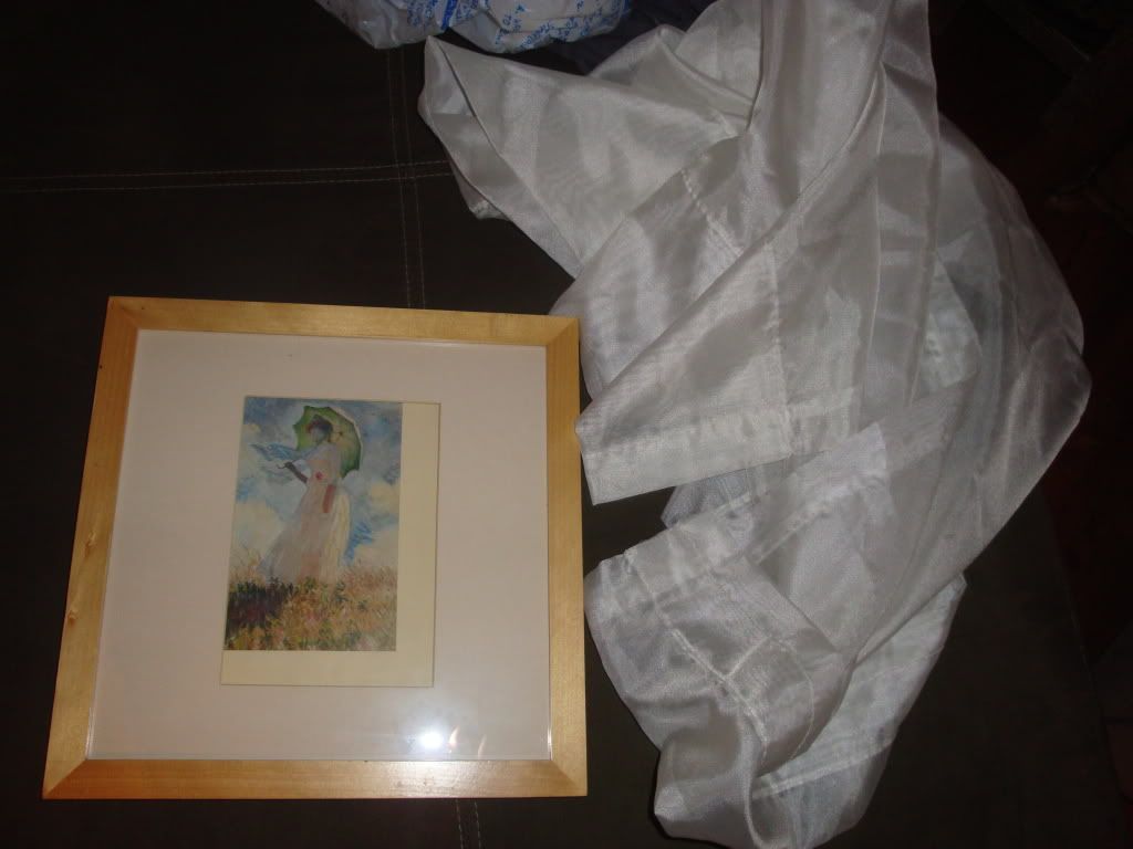
I began by going to the good will, finding a flat front picture frame ($1):

and a meshy silky fabric (curtains) that were like $4.


I removed the photo matte and glass and using a staple gun stapled a piece of the fabric tight over the front of the frame like canvas for a painting.

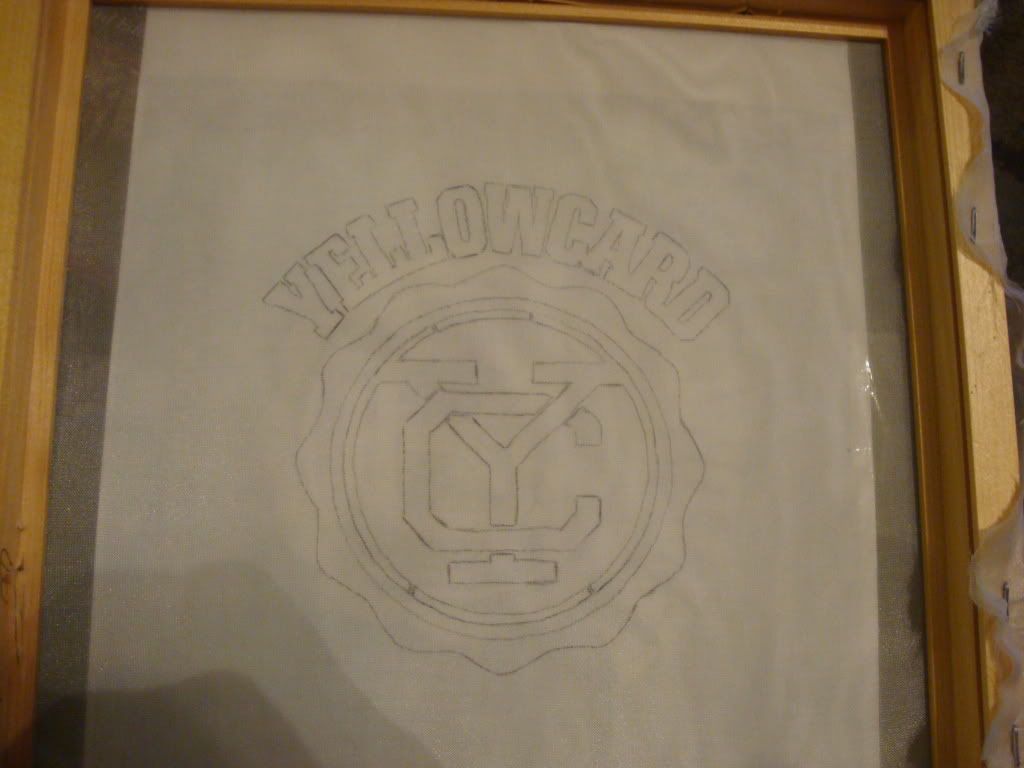
Next I chose my image and used a pencil to trace it onto the "silkscreen."

I used yellowcard's new logo for their new album that is about to come out since I don't have any yellowcard shirts and I like them.


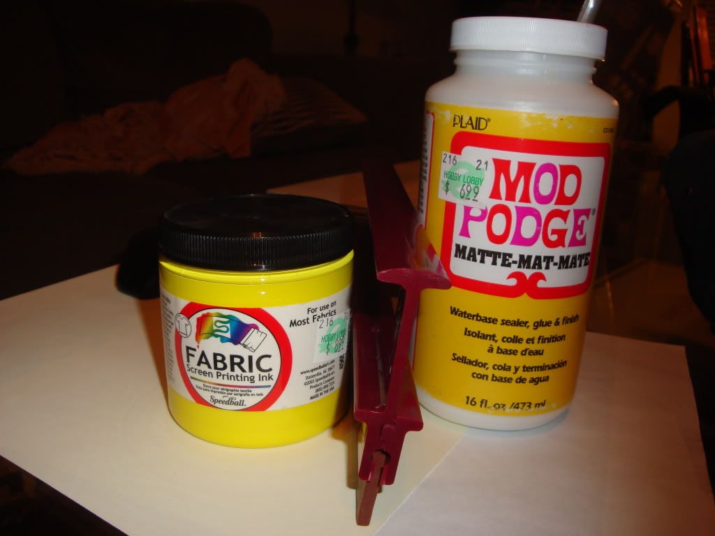
Here's the rest of my supplies. I used a paint bursh to brush the "mod podge" glue stuff onto anywhere I didn't want ink to go through creating a stencil.


After it dried it looked like this:


Now I'm ready to print. I set the stencil on top of my blank t-shirt with cardboard between to keep it from bleeding, spooned a little bit of the yellow dye/paint onto the stencil and using a squeegee ran it across the stencil. After that I removed the stencil and used an iron to warm and dry the ink.

Here is the finished result! Not too shabby! Pretty good for a first try!


Next time I'll try photo emulsion as it is more intricate and usually turns out better.

Wednesday, February 9, 2011

LED Dog Collar

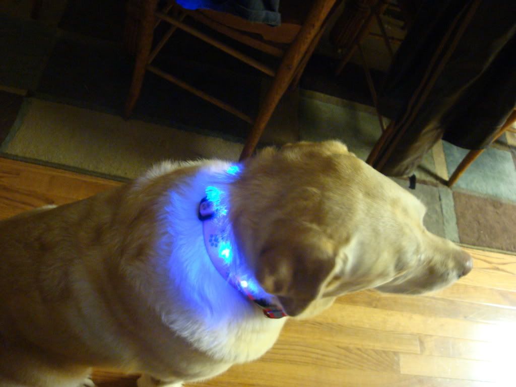
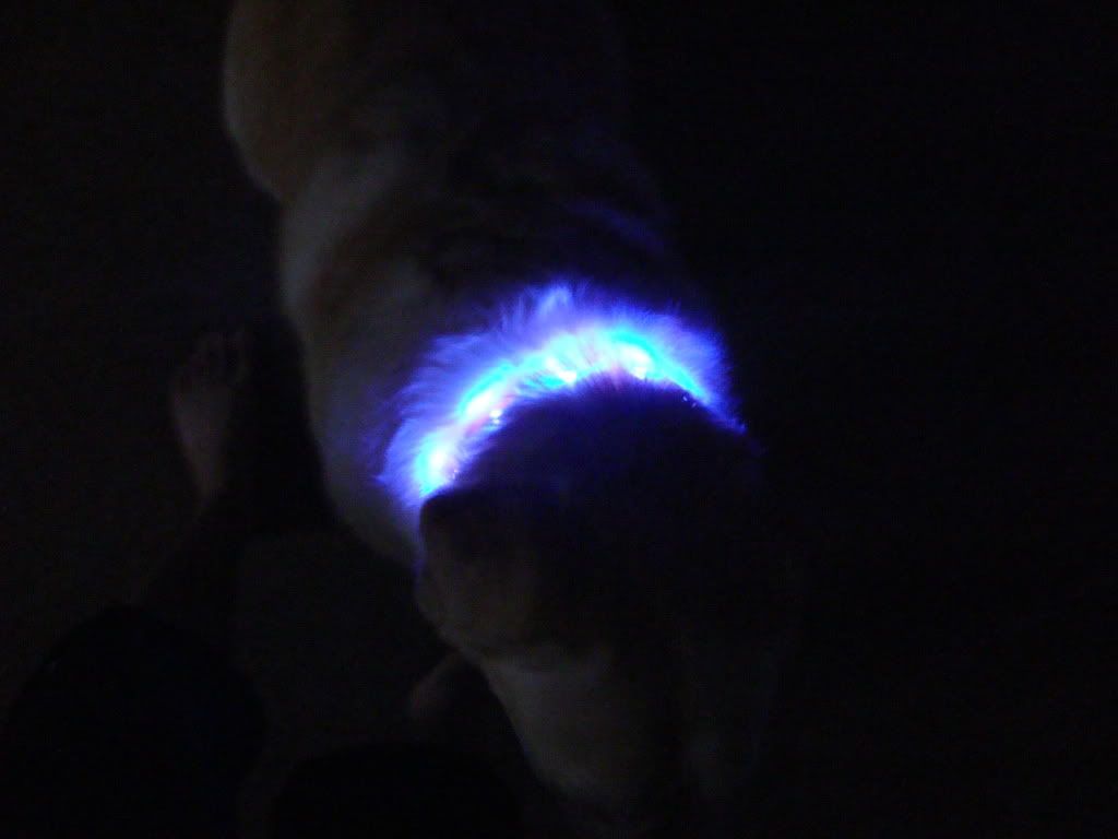
So this is a pretty simple project, but I thought it was a clever idea. I have 2 dogs, a lab and a lab mix. The lab "Sunshine" likes to runaway a lot if we let her outside at all. She always comes back, but we can't find her whenever she leaves. This worries us sometimes because we don't want a car to hit her, especially at night. Anyways, my idea came from this that I could make some type of collar that at least at night, would make her more visible.

Thus came the idea of a LED dog collar. Now, this basic one has to be turned on and off (which means that I would have to let her out on purpose to use it) but it is just a prototype. I have ideas about how to make it automatically turn on, but more on that later.

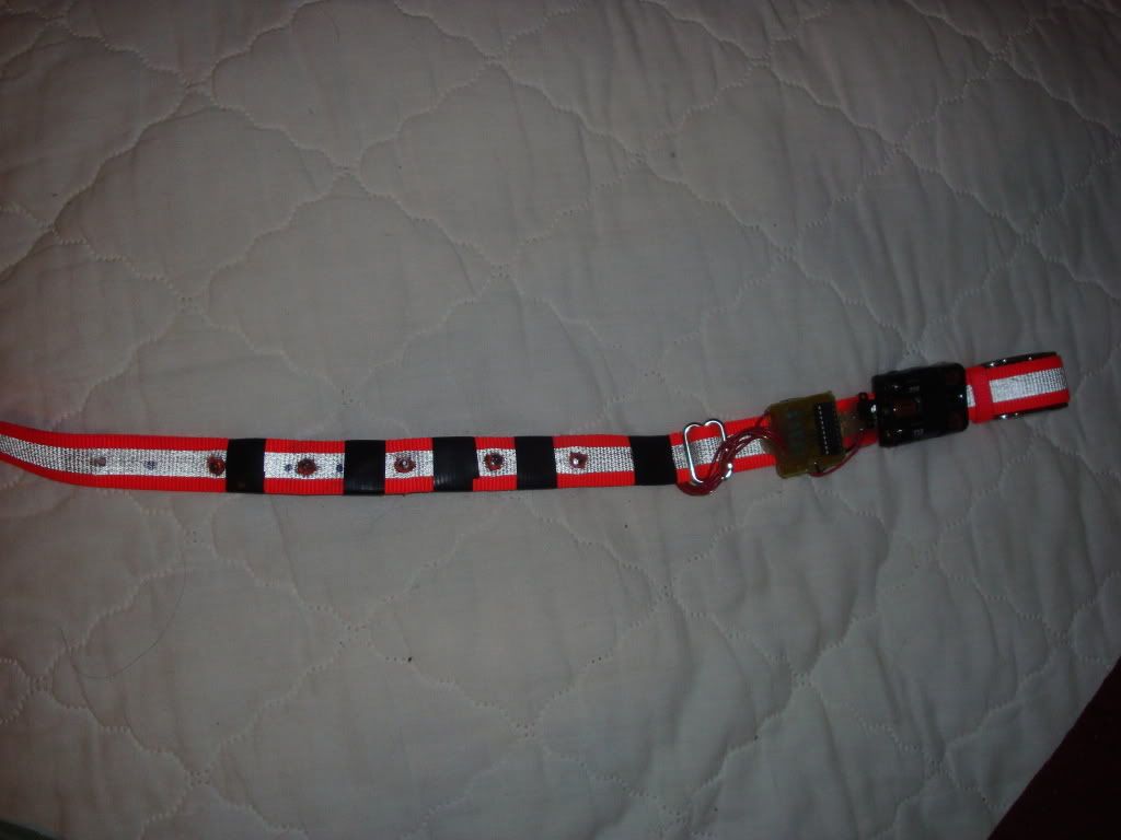
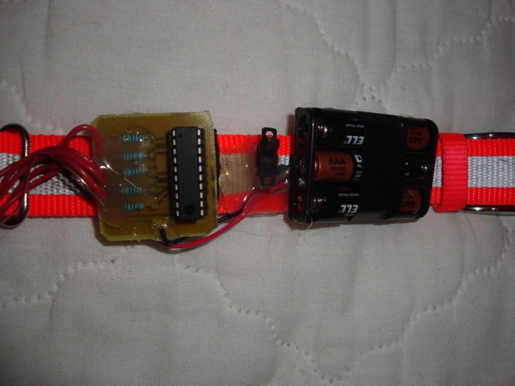
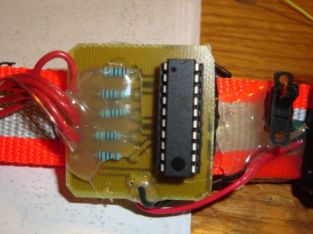
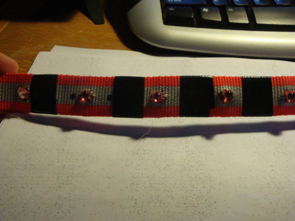
So the collar runs off an Atmel AVR ATTINY2313. It has 5 blue LEDs, and is powered by 3 AAA batteries. I also etched a custom circuit board (toner transfer method) and then covered most of the components in hot glue. The LEDs and all the wires on the collar are also mounted using hot glue. Now I definitely could have used a smaller avr, but the attiny2313 was the only micro I had lying around other than my bigger ATMEGA 328 from the arduino which I used as an ISP to program the tiny. The code is very simple, written in C, it just does several different strobe and "police light" patterns. Like I said before the device has a switch to turn it on and off.

Here are some photos and a video of it in action:


Now I was talking about the switch before, how it seems kind of pointless for the original intent of the collar (in case my dog runs away). So I was thinking, how do I trigger the LED collar to come on when my dog is outside? Well, I thought one idea, since it is winter right now, it is much colder outside. So if I hooked a temperature sensor up to the MCU, I could cause low temperatures to activate the LEDs. Just an idea, still a work in progress.


Video:

Hello

Well after seeing all the cool blogs all over the internet with peoples electronics projects on them, I sprang for it and decided to create a blog myself. Now, I don't know if anyone will actually read this, but I thought it would be a nice place to post all of the little projects and things I build.

For those of you who don't know me:
My name is Ken. I am an electrical engineering student at Tennessee Tech University. Some of my main interests and projects involve micro controllers (though I am pretty new to them) and also my saltwater aquarium. So this blog is going to be where I post many of them.

Anyways enjoy the blog!